|
|
 |

Although the microprocessor and digital network technologies have fundamentally reinvented the ways in which today's data acquisition systems handle data, much laboratory and manufacturing information is still communicated the "old" way, via analog electrical signals. And a fundamental understanding of how analog signal transmission works must first begin with a discussion of electrical basics.
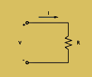
To understand the ways in which an analog signal is transmitted over a circuit, it is first important to understand the relationships that make analog signal transmission possible. It is the fundamental relationship between voltage, current, and electrical resistance (Figure 3-1) that allow either a continuously varying current or voltage to represent a continuous process variable.
 |
Figure 3-1:A Basic
Electric Circuit |
While charge flow is electric current, voltage is the work done in moving a unit of charge (1 coulomb) from one point to another. The unit of voltage is often called the potential difference, or the volt (V). The International System of Units (SI) unit for electrical flow is the ampere (A), defined as one coulomb per second (c/s).
A signal source of voltage, V, will cause a current, I, to flow through a resistor of resistance, R. Ohm's law, which was formulated by the German physicist Georg Simon Ohm (1787-1854), defines the relation:
V=IR
While most single-channel analog signal transmissions use direct current (dc) variations in current or voltage to represent a data value, frequency variations of an alternating current (ac) also can be used to communicate information. In the early 19th century, Jean Baptiste Joseph Fourier, a French mathematician and physicist, discovered that ac signals could be defined in terms of sine waves. A sine wave is described by three quantities: amplitude, period, and frequency. The amplitude is the peak value of the wave in either the positive or negative direction, the period is the time it takes to complete one cycle of the wave, and the frequency is the number of complete cycles per unit of time (the reciprocal of the period).
Analog Signal Types
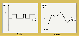
Most data acquisition signals can be described as analog, digital, or pulse. While analog signals typically vary smoothly and continuously over time, digital signals are present at discrete points in time (Figure 3-2). In most control applications, analog signals range continuously over a specified current or voltage range, such as 4-20 mA dc or 0 to 5 V dc. While digital signals are essentially on/off (the pump is on or off, the bottle is there or isn't), analog signals represent continuously variable entities such as temperatures, pressures, or flow rates. Because computer-based controllers and systems understand only discrete on/off information, conversion of analog signals to digital representations is necessary (and discussed in Chapter 1).
Transduction is the process of changing energy from one form into another. Hence, a transducer is a device that converts physical energy into an electrical voltage or current signal for transmission. There are many different forms of analog electrical transducers. Common transducers include load cells for measuring strain via resistance, and thermocouples and resistance temperature detectors (RTDs) for measuring temperature via voltage and resistance measurement, respectively. Transmission channels may be wires or coaxial cables.
 |
| Figure 3-2:Digital and Analog Signal Representations |
For noise-resistant transmission over significant distances, the raw transducer signal is often converted to a 4-20 mA signal by a two-wire, loop-powered transmitter. The bottom value of a process variable's range, for example, a temperature, is typically designated as 4 mA, making it easy to distinguish transmitter failure (0 mA) from a valid signal. If the current source is of good quality, current loops tend to be less sensitive to noise pickup by electromagnetic interference than voltage-based signals.
|


