|
|
 |

Network Topologies
The term topology refers to the method used to connect components on a network. The most common topologies are ring, bus, and star topologies (Figures 4-5, 4-6, and 4-7), but they can take on the appearances of each other and still maintain their characteristics. For example, a token ring network segment can be wired in a star configuration, where components are cabled back to a hub where the ring is "inside" the hub. This allows a common wiring closet for a given building or area with home-run cable pulls for each component. A hub offers the advantages of centralized maintenance and configuration control.
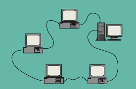 |
| Figure 4-5: Ring Network Topology |
Token Buses & Rings
The MAC functions of token rings and buses are similar. ARCnet, developed by the Datapoint Corp. in the '70s, is a token passing protocol that can be implemented in a bus or star topology using coaxial or UTP cables. A "token" is passed around the bus or ring. Whichever node has the token is allowed to communicate on the media. ARCnet runs at 2.5 Mbps, at the following lengths:
400 feet with 10 nodes using UTP;
2,000 feet with a practical limit of up to 100 nodes using RG-62 coaxial cable in a coaxial star configuration (using a hub or hubs); and
1,000 feet with 10 nodes per 1,000 foot segment using RG-62 coaxial cable.
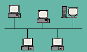 |
| Figure 4-6: Bus Network Topology |
ARCnet uses active and passive hubs in the star configuration, with network cards on the devices that have switches for setting node numbers. The lowest numbered node is the master controller, giving permission to communicate to each node by number. ARCnet is available in a 20-Mbps version.
The IBM token ring protocol, standardized via IEEE-802.5, runs at 4 or 16 Mbps. Nodes on the ring connect to a multi-station access unit (MAU), a type of hub. MAUs can be connected together in a main ring, with segments, or lobes, from each MAU connected in a star configuration to devices with network interface cards. The length of the ring is limited to 770 meters and the maximum number of nodes allowed on a ring is 260 using STP cable. STP cable (150 ohm) is used most often, but UTP (100 ohm) cable can be used if passive filtering is provided for speeds up to 16 Mbps. Bridges can be used to connect rings.
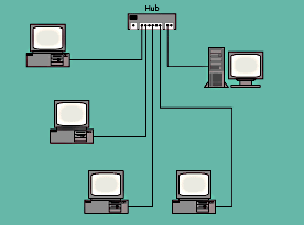 |
| Figure 4-7: Star Network Topology |
Jitter is an interesting problem that can arise on token ring networks, where nodes that are supposed to be synchronized with the master node receive distorted waveforms due to cable attenuation. The result is that each node operates at a slightly different speed. Jitter restricts the number of nodes allowed on the ring (72 at 16 Mbps on UTP). Jitter suppressors are available that can help alleviate this problem.
Repeaters are available for extending the ring. Using phase-locked-loop (PLL) technology, a repeater can extend the main ring an additional 800 feet at 16 Mbps on Category 5 copper UTP.
Using a media converter, or fiber optic transceiver, conversion between copper and single mode or multimode fiber is possible, thus extending main ring lengths or lobe lengths up to 1.25 miles.
Ethernet, or CSMA/CD
The most common bus topology in business applications is Ethernet. Ethernet originally was developed by the Xerox Corp., and later improved in association with Digital Equipment Corp. (DEC) and Intel. IEEE-802.3, based on the Ethernet standard, specifies a Carrier Sense Multiple Access with Collision Detection (CSMA/CD) media access control protocol. This network standard provides functionality at the first two OSI network layers-the physical and data link layers.
This MAC protocol allows independent transmission by all nodes on a network segment. A node sends messages down the segment with data, addressing, and control bits. All other nodes "see" the message, but only the node with the destination address will acknowledge and receive the message. When the sending node is using the segment (transmitting), all other nodes with messages to send "hear" the carrier and do not send. This type of protocol is known as "listen before send." If two nodes attempt to send at the same time, a collision is detected, and both nodes stop sending, wait a small, random amount of time, and resend. Where there is a lot of network traffic, many collisions can occur and overload the system.
The Ethernet CSMA/CD standard can be implemented in five different ways:
10Base5-standard "thick" coaxial cable;
10Base2-"thin" coaxial cable;
10BaseT-UTP;
100BaseT-UTP; and
10BaseFL or FOIRL-fiber optics.
The XBaseY nomenclature is interpreted as follows: X = the signaling rate in Mbps, and Y = some indication of the media type. The "Base" portion of the term means the signal uses the cable in a baseband scheme (as opposed to a broadband, multi-frequency, multi-channel modulating scheme).
10Base5 is a standard Ethernet implementation that uses RG-58 coaxial cable segments up to 500 meters long. Transceivers are clamped on to the segment, with a minimum distance between transceivers of 2.5 meters. A transceiver cable (or spur) connects the transceiver to the network node or device; this cable can be up to 50 meters in length. The maximum number of transceivers allowed is 100 per segment, and both ends of each segment are terminated with a 50-ohm resistor. Transceivers can be connected to hubs for fanning out to network nodes.
The 10Base2 "ThinNet" does not use a long coaxial segment with transceivers. Instead, modular repeaters are used with ThinNet modules in a star configuration. Thin coaxial cable is terminated with "T" connectors on network nodes, with multiple nodes connected in series on a segment, with one end of the cable home-run back to the repeater. The maximum length of a series segment is 185 meters, with a minimum distance between nodes (T-connectors) of 0.5 meters. No more than 30 nodes are allowed on a segment. 50-ohm terminators are required at each end of a segment.
The 10BaseT implementation uses UTP cable, with best results from Category 5 copper. Nodes are connected to a hub in a star configuration. The maximum length of one segment is 100 meters.
The 10BaseFL implementation uses 50, 62.5, or 100-micron multimode fiber optic cable. Fiber transceivers are available for connecting to network interface cards that do not support fiber.
Repeaters can be used to connect 10Base5 segments together up to 2,500 meters, and components and smaller networks can be linked together with interface devices to join the various media types into a larger network.
The IEEE-802.3 standard covers several CSMA/CD implementations, with lengths up to 925, 2,500, and 3,600 meters. The number of nodes allowed follows the hardware and performance requirements of the network operating system. More nodes and higher traffic mean more potential for collisions. Network performance might drop when you need it the most, such as during a plant transient when data flow and control element actuations are high.
Ethernet or CSMA/CD is established for 1, 10 and 100 Mbps, with 10 Mbps currently being the most common. Some vendors are offering "fast" Ethernet at 100 Mbps, compatible with existing 10 Mbps implementations. 100BaseT is essentially 10BaseT, only 10 times faster. They both use the same MAC layer. At higher speeds, implementations should account for round-trip delays for collisions.
Finally, a wireless Ethernet implementation is available. It supports data rates up to 3 Mbps through open spaces up to 3,000 feet and indoors from 200 to 600 feet, and line of site is not required indoors. Wireless repeaters and bridges are available to link cells together.
Decisions regarding local area network (LAN) topologies and MAC protocols can affect the way a network is managed for years to come. A new facility can be wired with state-of-the-art network components and premise wiring devices, but the network administrator or plant engineer is usually faced with an existing infrastructure, where options are constrained by installed media. For example, an old, abandoned 4-20 mA dc current loop STP cable can always be used to implement 10BaseT Ethernet and save considerable project funds. Or, a new fiber optic cable can be purchased with multimode fibers for this year's low bandwidth project and still have spare, single-mode fibers for future, high bandwidth applications.
Token passing and CSMA/CD protocols make interesting comparisons. Token passing offers a predictable access window with consistent performance on large, busy networks, but nodes need to wait for the token and large rings can result in significant delays. CSMA/CD allows a node to transmit immediately when the network is quiet, but performance can be unpredictable and depends on the probability of collisions.
Upgradeability and growth are two areas that should be considered for each new segment or modification to a given segment. The challenge is to keep an eye on network demands as new applications come along, and select the right amount of bandwidth and upgradeability for the dollar.
Moving Up the Layers
So far, the physical layer has been described, with implied functions at the data link and network layers. Two devices can communicate by way of a simple RS-485 link or they can be part of a larger LAN with complex media access controls.
The data link's only function is to pass data from one node to the next. The data link layer can connect two nodes or devices with a "bridge." Early bridges only connected two segments of a network with the same protocol (such as CSMA/CD or token passing). Smart bridges are available now that can connect differing protocols, with selective forwarding of data packets. Various levels of data link performance exist depending on the size of the network (wide vs. local area network; WAN vs. LAN) and the protocol/media selections.
The network layer routes incoming data for another node onto an appropriate outbound path. The physical device that performs this function is naturally called a router. Since bits still need to be pushed down some physical media, a router inherently performs the physical and data link functions in order to go up and down the OSI model, although routers are not sensitive to the data link and physical layer details, allowing them to connect different types of networks. A router takes an incoming packet, looks at the destination address, determines the best route, and provides the required addressing. One common implementation of this function is Transmission Control Protocol/Internet Protocol (TCP/IP). On Novell networks, this function is called Sequenced Packet Exchange/ Internetwork Packet Exchange (SPX/IPX). Novell, Inc. is perhaps the largest and most popular provider of network operating system (NOS) software. Novell provides CSMA/CD and token passing options.
The TCP and SPX protocols operate at the transport layer, and the IP and IPX layers operate at the network layer. Thus, routers send and receive packets between nodes with "IP addresses." The downside is that routers can only exchange data between nodes using the same network layer protocol.
Gateways operate at the network layer or above; they are used to connect dissimilar networks or systems via network protocol conversion.
The term "stack" refers to pieces of the OSI model that are bundled together. In client-server models, the TCP/IP software is sometimes referred to as a stack.
For example, on a PC with a network interface card, a word processor program (application), operating system (Windows NT), and redirector are at work (redirectors intercept network application I/O requests alongside a device's operating system). In this example (Figure 4-8), a user wants to open a file stored on a remote file server on another network by clicking on the G drive in the list of available drives (including the local A, B, and C drives). The redirector sees the I/O request, recognizes its external location, and sends it to the network interface card. On its way, the request goes through the TCP/IP stack where addressing and protocols at the transport and network layers are handled. The network interface card receives the request and holds it until it can get on the network and pass it on (push the bits) to the next node. The request is sent from node to node, using appropriate IP addresses and protocols until it gets to the server, where it is processed, and the reply is sent back essentially the same way.
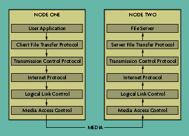 |
| Figure 4-8: A Remote File R equest According to OSI |
Backbones
In larger enterprises, some sort of information backbone, or data highway, allows high speed, high quality internetworking with good reliability. Backbones connect LANs, WANs and other forms of network segments together in one large network. The decision to build a backbone depends on the present and future needs of the enterprise. But once it is implemented, growth becomes less painful. One common backbone is the Fiber Distributed Data Interface, or FDDI standard. This backbone is also available in a copper version (CDDI).
FDDI is considered an implementation of a "metropolitan" LAN, or MAN. It is a dual-ring topology that can span up to 200 kilometers at 100 Mbps. It is commonly used to connect LANs together where higher bandwidths are required. Two rings of fiber carry data. All nodes attach to at least the primary ring, with some or all attached to the secondary ring. The idea is that if one ring breaks, the other automatically picks up the load. If both rings break at the same point, they automatically join together in one long ring (Figure 4-9).
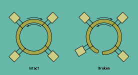 |
| Figure 4-9: Dual Ring Redundat FDDI Network |
FDDI hubs are available that bring together various FDDI devices, LANs, and Ethernet devices over single-mode or multimode fiber or copper. FDDI is a good choice for linking buildings together on a campus or industrial site.
Another implementation of an enterprise backbone, either stand-alone for one particular link or in conjunction with other technologies, is microwave technology. Operating at frequencies between 2 and 40 gigahertz (GHz), transmitters and receivers use long, line-of-site transmission paths. The economics are reasonable when compared with trenching and laying cable. The higher the tower, the longer the link (on the order tens of miles). Data rates are typically 1.544 Mbps. Leasing telephone lines is usually the alternative to microwave.
Satellite technology is just beginning to come into play for industrial and commercial network implementations. Remote transmitters for stationary platforms (such as well heads) or mobile platforms (as in the trucking industry) are being used to transmit real-time data via uplinks to a communications satellite and back down to ground stations. Telephone companies can provide switched services between the satellite system and a given enterprise network.
|


