|
|
 |

Physical Layer Options
There are a number of implementations of the physical layer. Network devices allow a wide range of connectivity options. Some networks are well defined using the OSI model, where cables, bridges, routers, servers, modems, and PCs are easily identified. Sometimes only a few devices are linked together in some kind of proprietary network, or where the network services are bundled in a black-box fashion with the device.
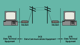
The most common serial data exchange interfaces are RS-232, RS-422, and RS-485 for connecting two or more devices together. All three interfaces use data terminal equipment (DTE) and data communication equipment (DCE) terminology (Figure 4-2). The DTE is the component that wants to communicate with another component somewhere else, such as a PC communicating with another PC. The DCE is the component actually doing the communicating, or, performing the functions of the generator and receiver discussed in the standards. A modem is a common example of a DCE.
 |
| Figure 4-2: Serial Data Transmission |
The interfaces between DTE and DCE can be categorized by mechanical, electrical, functional, and procedural aspects. Mechanical specifications define types of connectors and numbers of pins. Electrical specifications define line voltages and waveforms, as well as failure modes and effects. Functional specifications include timing, data, control and signal grounds, and which pin(s) the functions are to use. The procedural interface specifies how signals are exchanged.
RS-485 is another serial data transmission method. Officially, it is EIA 485, or "Standard for Electrical Characteristics of Generators and Receivers for Use in Balanced Digital Multipoint Systems" by the Electronics Industry Association (EIA). This standard defines a method for generating ones and zeroes as voltage pulses. Remember, for all the data handling, framing, packeting, routing and addressing performed by the upper layers, it still comes down to pushing ones and zeroes over some physical media.
What is important to know about RS-485 is that it allows multiple receivers and generators, and it specifies cable characteristics in terms of signaling speeds and lengths. A typical cable is a shielded twisted copper pair, which is adequate for the typical signaling rate of 10 million bits per second (Mbps). This standard only defines the electrical characteristics of the waveforms. Note that RS-485 does not specify any media control functions-that is strictly up to the device connected to the generator (usually a chip). RS-485 is generally good for cable lengths up to 2,000 feet.
One example of a simple serial network might be a series of recorders connected over an RS-485 link to a PC that receives data acquired by each recorder. The manufacturer sells a plug-in card that installs in each recorder, with wiring instructions. Each network card is daisy-chained to the others over a series of shielded twisted pair cables that ultimately terminate on a network interface card in the PC. There is no real need to know and understand the network layers in this arrangement, except to understand the limitations on RS-485 (distance, shielding, data rate, etc.).
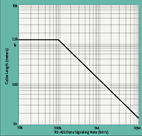
By title, the RS-422 standard is TIA/ EIA 422 B, "Electrical Characteristics of Balanced Voltage Digital Interface Circuits" by the Telecommunications Industry Association (in association with the EIA). It is similar to RS-485; the main differences being the rise times and voltage characteristics of the waveform. RS-422 generally allows cable lengths up to 1.2 kilometers at up to 100 thousand bits per second (kbps). At 10 million bps (Mbps), cable lengths are limited to around 10 meters (Figure 4-3). In the presence of cable imbalance or high common mode noise levels, cable lengths may be further reduced in order to maintain a desired signaling rate.
 |
| Figure 4-3: Cable Length vs RS-422 Data Rate |
RS-232C is perhaps the most common form of serial data exchange. It is officially known as EIA/TIA 232 E, "Interface Between Data Terminal Equipment and Data Circuit-Terminating Equipment Employing Binary Data Interchange," again by TIA in association with the EIA. The "E" suffix denotes a later version than the common "C" version. What makes this standard different from RS-422 and RS-485 is that it defines the mechanical as well as the electrical interfaces.
RS-232 is good for signal rates up to 20 kbps, at distances up to 50 feet. A zero (space) and a one (mark) are measured in terms of a voltage difference from signal common (+3 V dc = 0, -3 V dc = 1). The most common mechanical interfaces are the D-sub 9 and D-sub 25 connectors.
Interchange circuits (pins) in RS-232 devices fall into four categories: signal common, data circuits (transmitted data, received data), control circuits (i.e., request to send, clear to send, DCE ready, DTE ready), and timing circuits.
The standards described above all are used in serial communications schemes designed for longer distances.
There is one common parallel interface, known as the General Purpose Interface Bus (GPIB), or IEEE- 488. Up to 15 devices can be interconnected, usually personal computers and scientific equipment or instruments. It provides a high data signaling rate, up to 1 Mbps, but it is limited in length. The total bus length permitted is 20 meters, with no more than 4 meters between devices.
The IEEE-488 bus is a multi-drop, parallel interface with 24 lines accessed by all devices. The lines are grouped into data lines, handshake lines, bus management lines, and ground lines. Communication is digital, and messages are sent one byte at a time. The connector is a 24-pin connector; devices on the bus use female receptacles while interconnecting cables have mating male plugs. A typical cable will have male and female connectors to allow daisy-chaining between devices.
An example of an IEEE-488 implementation is a measurement system designed to assess the performance of a chemistry sample sink. The sink performs sample conditioning (pressure, flow, and temperature control) and chemical analysis (pH, dissolved oxygen, and conductivity) on water samples. The sink is instrumented with pressure sensors, resistance temperature detectors (RTDs), thermocouples, and reference junctions. A 30-point scanner is used to multiplex data from all of the sensors. The scanner is connected to a desktop or laptop PC using the GPIB interface. Data is acquired, stored, displayed, and reduced using application programs on the PC, efficiently and reliably under IEEE-488.
The media used to implement the physical layer is usually a set of copper wires. Unshielded twisted pair (UTP) cable is the most affordable. It is lightweight, easy to pull, easy to terminate, and uses less cable tray space than shielded twisted pair (STP). However, it is more susceptible to electromagnetic interference (EMI).
 |
Figure 4-4: Shielded Twisted Pair (STP)
Cable Construction |
STP is heavier and more difficult to manufacture, but it can greatly improve the signaling rate in a given transmission scheme (Figure 4-4.). Twisting provides cancellation of magnetically induced fields and currents on a pair of conductors. Magnetic fields arise around other heavy current-carrying conductors and around large electric motors. Various grades of copper cables are available, with Grade 5 being the best and most expensive. Grade 5 copper, appropriate for use in 100-Mbps applications, has more twists per inch than lower grades. More twists per inch means more linear feet of copper wire used to make up a cable run, and more copper means more money.
Shielding provides a means to reflect or absorb electric fields that are present around cables. Shielding comes in a variety of forms from copper braiding or copper meshes to aluminized mylar tape wrapped around each conductor and again around the twisted pair.
Fiber optics are being used more often as user applications demand higher and higher bandwidths. The term "bandwidth" technically means the difference between the highest and lowest frequencies of a transmission channel, in hertz (Hz). More commonly, it means the capacity or amount of data that can be sent through a given circuit.
A bandwidth of 100 Mbps is standard using fiber optic cables. When first introduced, fiber was considered only for special applications because it was expensive and difficult to work with. In recent years, the quest for greater bandwidth combined with easier-to-use fiber have made it more common. Tools and training for installing and troubleshooting fiber are readily available.
There are three basic fiber optic cables available: multimode step index, multimode graded index, and single mode. Multimode fibers usually are driven by LEDs at each end of the cable, while single mode fibers usually are driven by lasers. Single mode fibers can achieve much higher bandwidths than multimode fibers, but are thinner (10 microns) and physically weaker than multimode. Equipment costs for transmitting and receiving single mode fiber signals are much higher (at least four times) than for multimode signals.
One distinct advantage of fiber optic cables is noise immunity. Fiber optic cables can be routed indiscriminately through high noise areas with impunity, although fire ratings should be observed. Cables that pass through multiple spaces in a plant should be rated for heating/ ventilation/air conditioning (HVAC) plenums where they can withstand fires per National Fire Protection Association (NFPA) requirements.
|


